M2: GENERATING
DESIGN THROUGH
PROCESSES
In this second module module, we explored digital fabrication and parametric software as a means of design process using the Rhino and Grasshopper softwares. The task itself is divided into two parts: task A involved exploring volumes and 3D printing techniques, along with subtractive and additive processes, while in task B we learned about surfaces and laser cutting techniques.
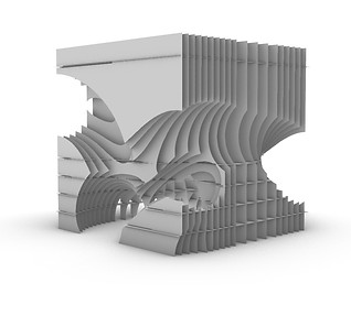
precedent study
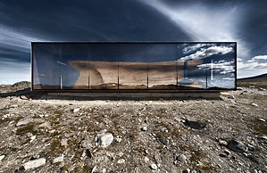
Taking what I learned from M1 of digital design, I wanted to take further the concept of designing with curvilinear forms and focusing on the interplay between light and shadow and understanding how they create a spatial experience and contribute to how spaces are utilized. Furthermore, one of the key features I admire from the Reindeer pavilion was the idea of designing within a rectangular box, so I wanted to keep this idea in mind when designing the fragments.
task A: subtractive and additive processes
In the first task, we used Grasshopper to create a design based on a 100x100x100 grid and extracted a 50x50x50 fragment from it.
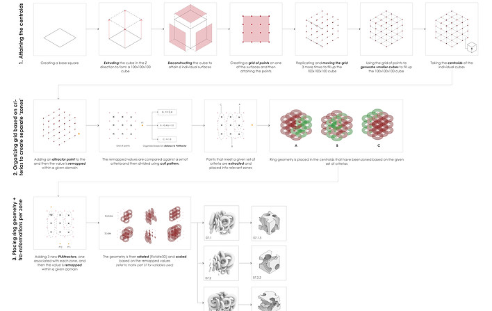
The final geometries were derived by a step-by-step process than involves controlling and manipulating the parameters and analysing the effects of subtractive and additive processes on the solids. The parameters were chosen and controlled based on what my 'end goal' was; which, in this case, was to create curvilinear forms and voids in the solids.
Using the 100x100x100 as the base for the geometry, I divided the box into smaller cubes and I extracted the centre points of the cubes and assigned the ring geometry to each of the points. Afterwards, each geometry was manipulated based on a set of criterias to create intersections and voids.


As part of the documenting process, all the key changes made during the iteration process was recorded in a matrix.
key iterations
iteration 1: 07.1.5
Iteration 1: 07.1.5
Iteration 1 focused on the creation of complex vertical cuts around the cube to allow for vertical sunlight penetration and maintaining the center part of the cube as a means of separating the spaces.

iteration 2: 07.2.2
Iteration 2: 07.2.2 (rotated)
Iteration 2 focused on the creation of diagonal cuts through the cube using the chosen geometry. The top is fully concealed to create a darker, more intimate space. Voids are created on the sides for sunlight penetration from one side of the cube to another.

iteration 3: 07.3.1
Iteration 3: 07.3.1
Iteration 3 focused on the creation of horizontal cuts through the cube While the intersections between the rings resulted in voids, areas where the rings do not touch resulted in interesting intersections, which act as visual / physical obstructions.

For task A, Iteration 2 was chosen as the main fragment. In terms of spatial quality, the ring geometries resulted in voids and intersections, especially in the bottom part of the geometry. As seen on the drawing, the bottom part is almost empty and the ‘ceilings’ were curvy as a result of the ring geometry cuts. When I saw this, I decided that this fragment could be utilized as a pavilion where people could walk under and around it.


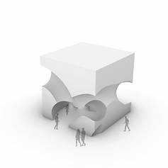
At 8:1 scale, the fragment can be used as an individual seat. This smooth surface on the top of the fragment creates a comfortable surface for sitting and the bottom part of the fragment creates visual interest to the seat.
At 70:1 scale, the fragment (which has been rotated) acts a more interactive space. The areas can be used as seating spaces, places to lean or even stand on. By rotating the geometry, more light can penetrate to the space.
At 200:1 scale, the fragment acts as a superstructure pavilion where people can walk under and through the pavilion. The closed off top minimises light penetration during the day, thus creating more intimate spaces. Rather, light enters through the sides of the fragment.
task B: section and waffle structures
In task B, we took what we made in task A to reconstruct the geometry through waffling and sectioning techniques. The chosen geometry from task A was iteration number 2.
For this task, I experimented with both XY waffles and radial waffles. I started the first iteration by experimenting with XY waffles on all 3 geometries from Task A. Eventually, I decided to work with the Iteration number 2. However, in the process of doing so, I discovered that the XY waffles were not the most suitable direction simply because the curves and voids in the geometry caused a lot of problems in terms of constructibility. Hence, I decided to make use of the YZ waffles. Additionally. I created a pattern to control how I want the contours to be spaced and how they intersect to create the noggings.
For the radial waffle, I made changes towards the number of radial contours and also the location of the top and bottom rings. By increasing the number of radial contours, I was able to better capture the curvy forms, which are key aspects of my design. By changing the location of the top and bottom rings, I learned that I could maximize the bottom space to increase the area of accessible spaces.
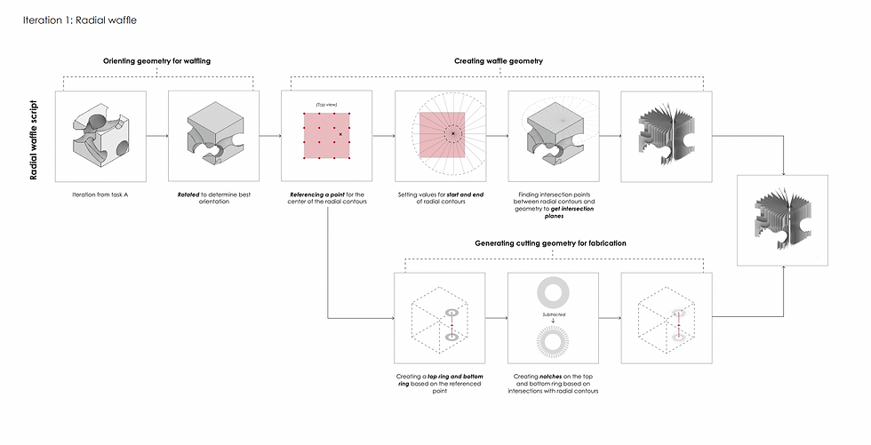


As part of the documenting process, all the key changes made during the iteration process was recorded in a matrix.
yz waffle
Because of the constraints and challenges of that this geometry caused to the nesting and waffling process, I decided to use an YZ waffle. Similar to task A, this structure minimizes light penetration from the sky, rather, light comes through the voids created by the intersections between the contours (on the sides of the cube).

radial waffle
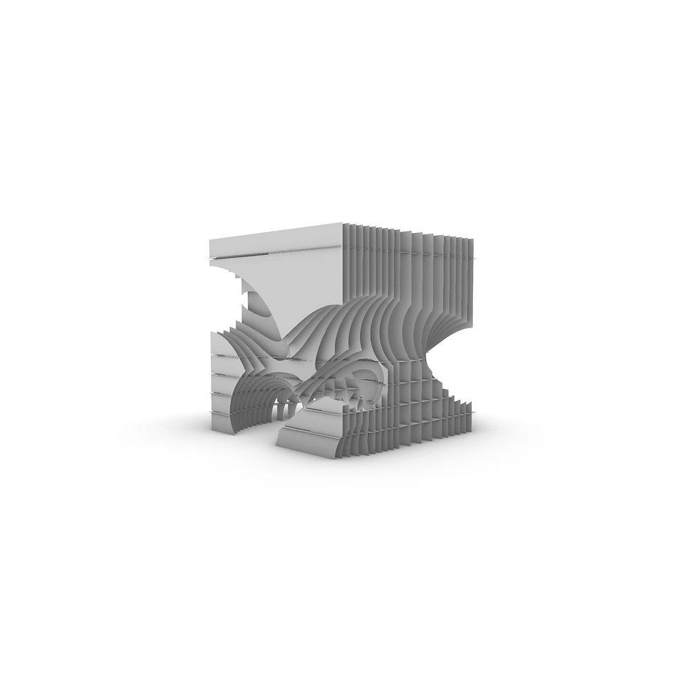
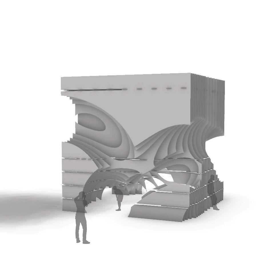
For the radial waffle, I admire the way the contours originate from one point and radiate outside (hence the name). This structure creates a more open and inviting feel (as seen in the space test). Although the same geometry was used, the contours resulted in a different spatial experience. The visual obstructions became less prominent due to the spaces between the contours. Sunlight also penetrates more easily from all directions as the geometry is not as closed off.


key iteration
For task B, the radial waffle became the key iteration because I admire the way the contours originate from one point and radiate outside (hence the name). In contrast to Task A, this structure creates a more open and inviting feel. Although the same geometry was used, the contours resulted in a different spatial experience. The visual obstructions became less prominent due to the spaces between the contours. Sunlight also penetrates more easily.


lasercut fabrication

As part of task B, we were asked to layout the waffle elements on a nesting template so they could be printed and laser cut. Prior to laying out the template, I had to ensure that my waffle model could be physically constructed, without actually printing out the lasercut. Once I figured that out, I started to lay out the template. One of the biggest challenges was arraying them in a way where the space could be used efficiently - and this was done by laying out the template carefully and lining up the individual elements so they could be cut efficiently (for instance, lines are arranged together so they could be cut at once).